
Module A-190-8 is a Midi/USB to Sync interface. The main application of the module is the control of clocked A-100 modules like sequencers (A-155), sequencer controllers (A-154), trigger divider (A-160 or A-163), trigger sequencer (A-161) and similar units. It may be used also to reset or sync LFOs (e.g. A-145, A-147, A-143-4) or to trigger envelope generators (A-140, A-141-2, A-143-1, A-143-2) with a fixed clock rate.
These are the most important features of this version of the module:
Midi input (recognizes only Midi realtime messages clock, start, stop and continue)
USB input for Midi via USB
Clock outputs:
96: outputs the Midi clock 1:1 (96 pulses per measure/ppm or 24 pulses per quarter note/ppq)
32: outputs the Midi clock divided by 3 (32 pulses per measure/ppm or 8 pulses per quarter note/ppq)
16: outputs the Midi clock divided by 6 (16 pulses per measure/ppm or 4 pulses per quarter note/ppq)
8: outputs the Midi clock divided by 12 (8 pulses per measure/ppm or 2 pulses per quarter note/ppq)
1: outputs a pulse at the start of each measure
Other outputs:
Start: outputs a pulse at each Midi Start or Continue message or generates a gate signal that remains in the high state until a Midi Stop message occurs (selectable via jumper)
Stop: outputs a pulse at each Midi Stop message
Reset: outputs a pulse at each Midi Start message that follows a Midi Stop message
Wait control input, can be selected by means of a jumper between Gate function or Switch function: in Gate mode the positive edge of a gate signal is used to init the Wait state, in Switch mode an external switch that connects to GND is used to init the Wait state (equivalent to Switch-Trigger)
Wait button / Wait control input: Whenever the Wait button is operated or a positive voltage is applied to the Wait input the module waits for the next measure start until the clock signals are generated.
LED displays for clock, "1" and start (display of Start depends upon the chosen Start mode, see above)
output voltages can be selected between +5V and +12V by means of an internal jumper (for DIN Sync applications +5V has to be used !)
firmware updates via USB (provided that there will be updates available)
- Width: 6HP
- Depth: 50mm
- Power: 50 mA +12V / 50 mA -12V
How much is my shipping?
Shipping is automatically calculated before you submit your payment information. Simply add items to your cart and proceed to the checkout page, where you'll be offered shipping options and their prices. In the UK, 'next working day' shipping is free if the order value is over £150, and £5 otherwise. We can also ship on a 'next working day before 12pm' service, which costs £6 for orders over £150 and £7.50 for orders under £150.
Do you ship to my country?
Almost certainly - the site will give you an estimate of shipping costs if you add an item to the cart and then enter your country and postcode. If you have specific requirements (such as if you prefer UPS over FedEx, for example) then let us know in advance and we'll try to work something out for you.
Shipping methods
We use a combination of DPD and Royal Mail for the UK, and for international orders it's either DPD, DHL, FedEx, UPS or Royal Mail depending on where you are in the world. If you have a particular preference then try to let us know BEFORE you order so we can look into it for you. Please note that there may occasionally be additional shipping charges if you live in a remote area, depending on what surcharges are applied by the shipper. We'll get in touch to discuss this with you in such cases.
Dispatch times
For UK orders, we normally dispatch the same working day if we get the order before 16:00. If you have a really urgent situation then of course drop us an email before ordering and we'll always do our absolute best to accommodate you.
For international orders, we normally dispatch the same day if we get the order before 13:00 but again, occasionally it might be the next day before we can send it out, and sometimes the couriers may come to collect a little earlier than scheduled which would also push an order into the next day.
Saturday/Sunday delivery
If you're in the UK and you order before 16:00 on a Friday then we can send something for a Saturday or Sunday delivery with DPD. This is FREE for order values over £350, £5 for order values between £75 and £250, and £7 for order values under £75. (NB: this applies to UK mainland addresses only). Please note that any orders placed after 16:00 on a Friday will ship on the Monday.
International shipping times
Most orders are delivered within 3 to 5 working days if sent on a courier service. Royal Mail services can take a lot longer and are often less secure.
Pre-orders
If a product is listed as a pre-order, it means we've ordered it from the supplier but it's not physically in stock yet. The product listing will include an estimated shipping date based on the best information we have from the supplier, but do bear in mind this is subject to change and is not a guaranteed date.
If you place an order containing a mixture of in-stock and pre-order items, we'll normally hold off on shipping anything until the pre-order item(s) have arrived, rather than splitting it into multiple shipments. If you need the in-stock items sooner, we'd recommend placing separate orders. As always, please get in touch if you have questions.
Product Overview
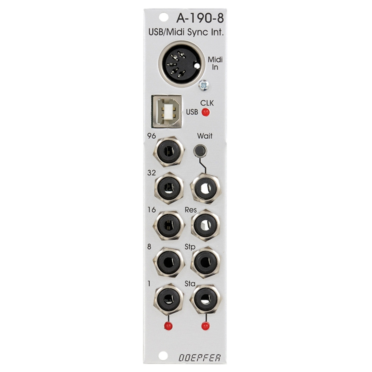
Module A-190-8 is a Midi/USB to Sync interface. The main application of the module is the control of clocked A-100 modules like sequencers (A-155), sequencer controllers (A-154), trigger divider (A-160 or A-163), trigger sequencer (A-161) and similar units. It may be used also to reset or sync LFOs (e.g. A-145, A-147, A-143-4) or to trigger envelope generators (A-140, A-141-2, A-143-1, A-143-2) with a fixed clock rate.
These are the most important features of this version of the module:
Midi input (recognizes only Midi realtime messages clock, start, stop and continue)
USB input for Midi via USB
Clock outputs:
96: outputs the Midi clock 1:1 (96 pulses per measure/ppm or 24 pulses per quarter note/ppq)
32: outputs the Midi clock divided by 3 (32 pulses per measure/ppm or 8 pulses per quarter note/ppq)
16: outputs the Midi clock divided by 6 (16 pulses per measure/ppm or 4 pulses per quarter note/ppq)
8: outputs the Midi clock divided by 12 (8 pulses per measure/ppm or 2 pulses per quarter note/ppq)
1: outputs a pulse at the start of each measure
Other outputs:
Start: outputs a pulse at each Midi Start or Continue message or generates a gate signal that remains in the high state until a Midi Stop message occurs (selectable via jumper)
Stop: outputs a pulse at each Midi Stop message
Reset: outputs a pulse at each Midi Start message that follows a Midi Stop message
Wait control input, can be selected by means of a jumper between Gate function or Switch function: in Gate mode the positive edge of a gate signal is used to init the Wait state, in Switch mode an external switch that connects to GND is used to init the Wait state (equivalent to Switch-Trigger)
Wait button / Wait control input: Whenever the Wait button is operated or a positive voltage is applied to the Wait input the module waits for the next measure start until the clock signals are generated.
LED displays for clock, "1" and start (display of Start depends upon the chosen Start mode, see above)
output voltages can be selected between +5V and +12V by means of an internal jumper (for DIN Sync applications +5V has to be used !)
firmware updates via USB (provided that there will be updates available)
Technical Specs
Shipping Details
How much is my shipping?
Shipping is automatically calculated before you submit your payment information. Simply add items to your cart and proceed to the checkout page, where you'll be offered shipping options and their prices. In the UK, 'next working day' shipping is free if the order value is over £150, and £5 otherwise. We can also ship on a 'next working day before 12pm' service, which costs £6 for orders over £150 and £7.50 for orders under £150.
Do you ship to my country?
Almost certainly - the site will give you an estimate of shipping costs if you add an item to the cart and then enter your country and postcode. If you have specific requirements (such as if you prefer UPS over FedEx, for example) then let us know in advance and we'll try to work something out for you.
Shipping methods
We use a combination of DPD and Royal Mail for the UK, and for international orders it's either DPD, DHL, FedEx, UPS or Royal Mail depending on where you are in the world. If you have a particular preference then try to let us know BEFORE you order so we can look into it for you. Please note that there may occasionally be additional shipping charges if you live in a remote area, depending on what surcharges are applied by the shipper. We'll get in touch to discuss this with you in such cases.
Dispatch times
For UK orders, we normally dispatch the same working day if we get the order before 16:00. If you have a really urgent situation then of course drop us an email before ordering and we'll always do our absolute best to accommodate you.
For international orders, we normally dispatch the same day if we get the order before 13:00 but again, occasionally it might be the next day before we can send it out, and sometimes the couriers may come to collect a little earlier than scheduled which would also push an order into the next day.
Saturday/Sunday delivery
If you're in the UK and you order before 16:00 on a Friday then we can send something for a Saturday or Sunday delivery with DPD. This is FREE for order values over £350, £5 for order values between £75 and £250, and £7 for order values under £75. (NB: this applies to UK mainland addresses only). Please note that any orders placed after 16:00 on a Friday will ship on the Monday.
International shipping times
Most orders are delivered within 3 to 5 working days if sent on a courier service. Royal Mail services can take a lot longer and are often less secure.
Pre-orders
If a product is listed as a pre-order, it means we've ordered it from the supplier but it's not physically in stock yet. The product listing will include an estimated shipping date based on the best information we have from the supplier, but do bear in mind this is subject to change and is not a guaranteed date.
If you place an order containing a mixture of in-stock and pre-order items, we'll normally hold off on shipping anything until the pre-order item(s) have arrived, rather than splitting it into multiple shipments. If you need the in-stock items sooner, we'd recommend placing separate orders. As always, please get in touch if you have questions.


")
")
